Tunney Bridge
Services Applied by VCS Engineering
 Small Project Award of the Year WINNER!
Project Introduction
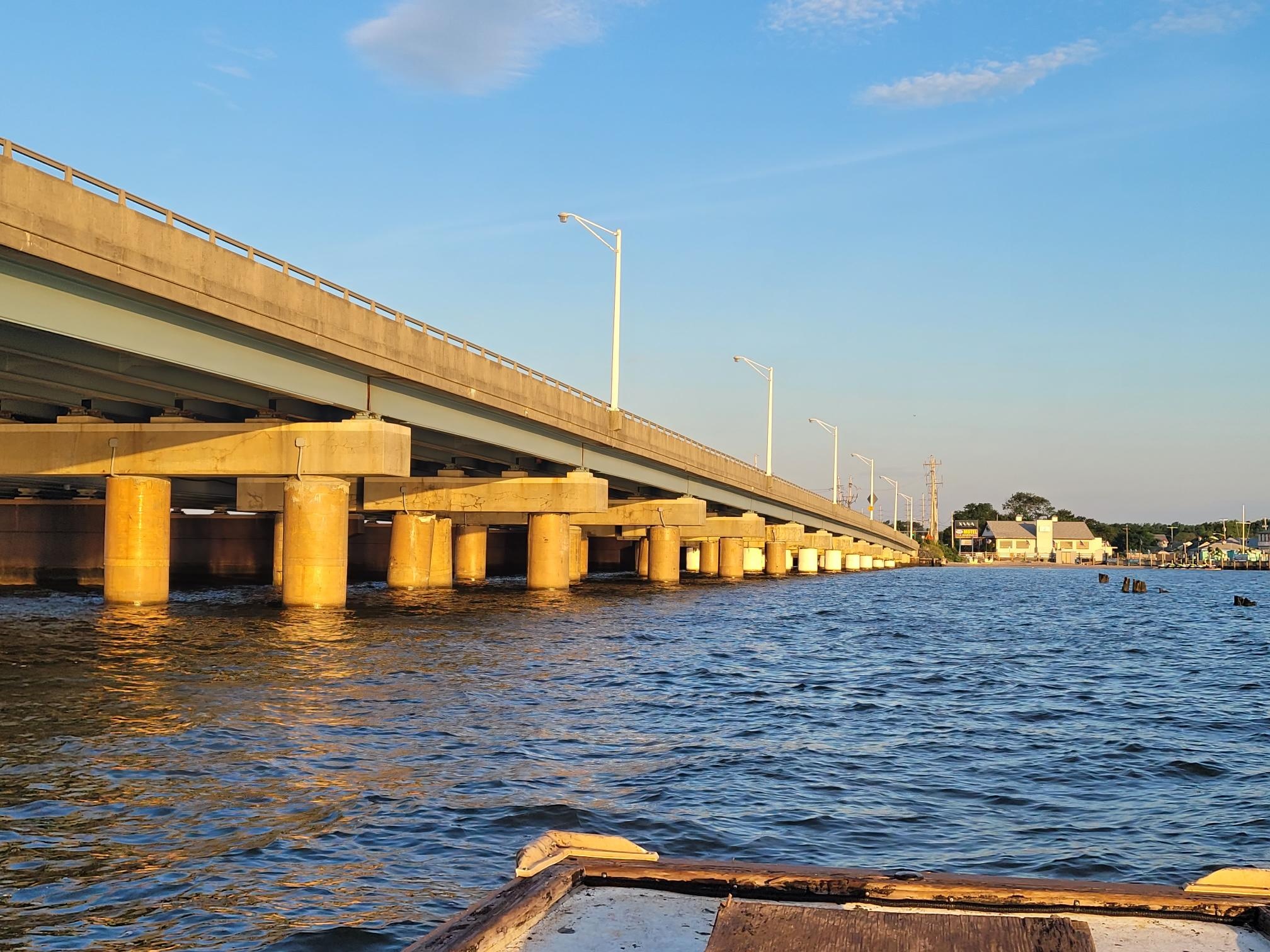
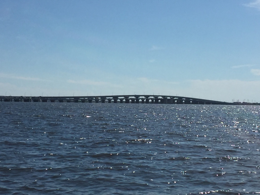
The J. Stanley Tunney Bridge carries NJ Route 37 Westbound over Barnegat Bay, connecting Toms River, NJ, and Seaside Heights, NJ, a famous vacation destination along the Jersey Shore. The Thomas A. Mathis Bridge carries eastbound traffic. Barnegat Bay is connected to the Atlantic Ocean by the Barnegat Inlet and contains brackish water, resulting in chloride exposure for the Tunney Bridge sub-structure.
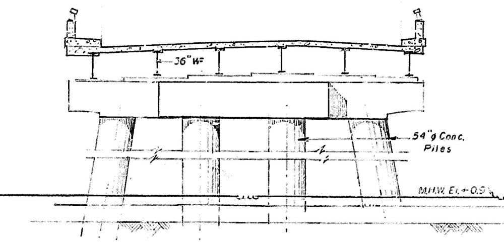
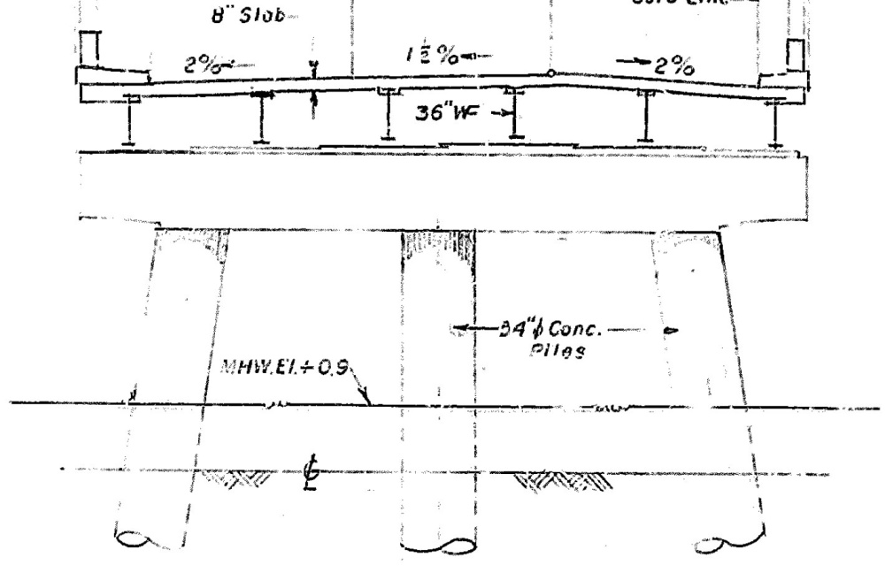
The Tunney Bridge was constructed in 1969, consists of 50 spans, and was designed to allow ship passage below the bridge. This 4,877 ft long bridge consists of a reinforced concrete deck, precast prestressed girders, and four different layout types of bents supported on 54-inch prestressed hollow cylindrical piles.
Inspection & Testing
Recently the routine bi-annual inspection was awarded to a new consultant. During their first inspection of the bridge, visual inspection identified wide-spread cracking in the piles ranging from hairline up to ½ inch wide. Sounding of the concrete did not identify any delaminations nor spalls of the concrete associated with these cracks. Upon identifying these cracks, the consultant’s first reaction was to review the past inspection reports to see if these cracks were new or had been present in previous inspections. This research determined that these cracks had been documented and present in the piles since 1987, although it is unclear how severe the cracks were at that time.
Chloride-induced corrosion begins with the breakdown of the reinforcing steel’s passive oxide film, created by the concrete’s natural alkalinity. Corrosion byproduct takes up more space than the original uncorroded steel which can lead to cracking in the concrete cover. The typical progression of concrete corrosion deterioration after initial cracking is concrete delamination (concrete separation parallel to the concrete surface) and eventual spalling, where segments of concrete separate from the structure.
Since the Tunney Bridge pile cracks were not associated with any delamination or spalling of the concrete,
the previous inspection teams assumed corrosion was not progressing and dismissed these cracks as a nonissue. However, the new consultant wanted a second opinion about these cracks and reached out to their corrosion and durability sub-consultant to review the cracks and determine if they are affecting the durability of the piles.
Testing Included:
- Ground Penetrating Radar (GPR) Survey to Determine Reinforcement Cover-Depth
- Corrosion Potential Survey
- Corrosion Rate Measurements
- Chloride Sampling
- Carbonation Testing
- Visual Inspection of Reinforcement in Select Openings
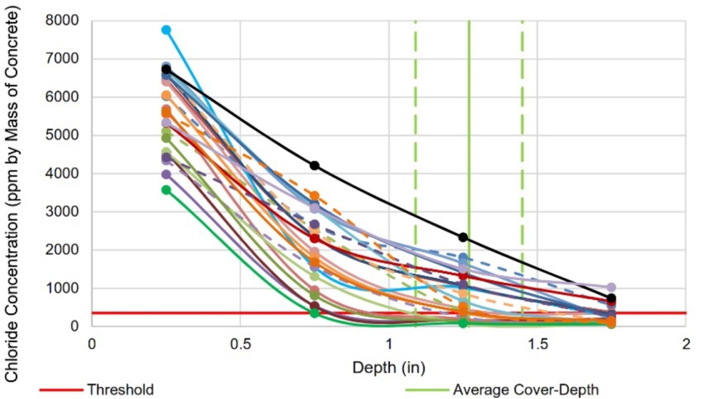
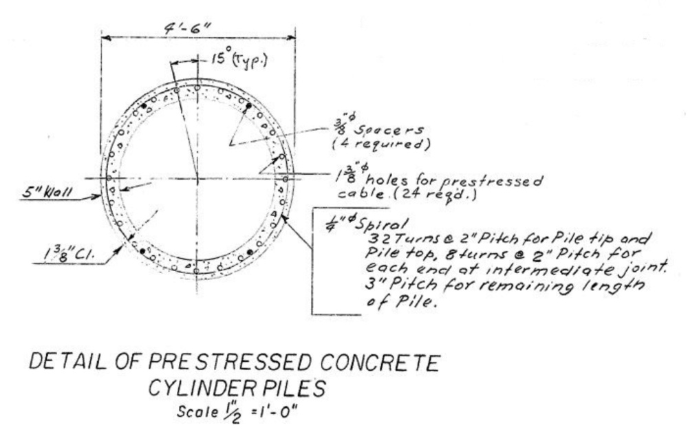
GPR measurements confirmed the low cover-depth specified in the original drawings at 1 3/8 in which in a direct marine exposure can have a significant affect on the concrete’s durability. Not surprisingly, chloride contamination of the concrete was severe, and in almost every sample collected, the chloride concentration at the reinforcement depth was well above the corrosion initiation threshold. Based on chloride data and corrosion potential measurements, VCS determined that active corrosion was present from the mud line up to 10-12 ft. above the high water line on most piles.
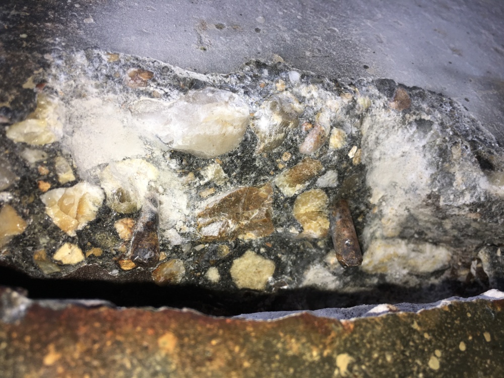
At various cracks, VCS performed openings to inspect the condition of the steel reinforcement. The openings at locations of large vertical cracks showed that the spiral reinforcement had completely corroded away inside the cracks, with 100% section loss. In every crack, any spiral reinforcement that crossed the crack was completely gone. These large vertical cracks allowed saltwater to directly access to the reinforcing steel and promoted severe localized corrosion of the spiral ties. These cracks also allowed the seawater to remove the initial soluble iron ions before iron oxides could precipitate inside the concrete, eliminating the pressure buildup mechanism that causes concrete delamination and eventual spalling. Therefore, no delaminations or spalls were formed due to this corrosion progression. Delaminations and spalls are formed due to the corrosion product buildup that causes tensile stress in the concrete, which eventually causes cracking and delamination. If the oxide forming in a wide crack is being washed out, it will not allow for the buildup of tensile stress to form a delamination. This allowed the severe localized corrosion to progress unchecked resulting in complete steel section loss without forming delaminations or spalls. Mistakenly, the previous bridge inspectors were waiting for the formation of delaminations and spalls to indicate the need for repairs, which significantly underestimated the severity of the cracks. With the experience of the current inspector and the involvement of a corrosion engineer, they were able to recognize the uniqueness of this situation and immediately address it.
Rehabilitation Approach
The rehabilitation had two goals:
- Strengthen the piles with the large cracks and substantial steel section-loss.
- Mitigate the corrosion activity of the piles to extend their service life.
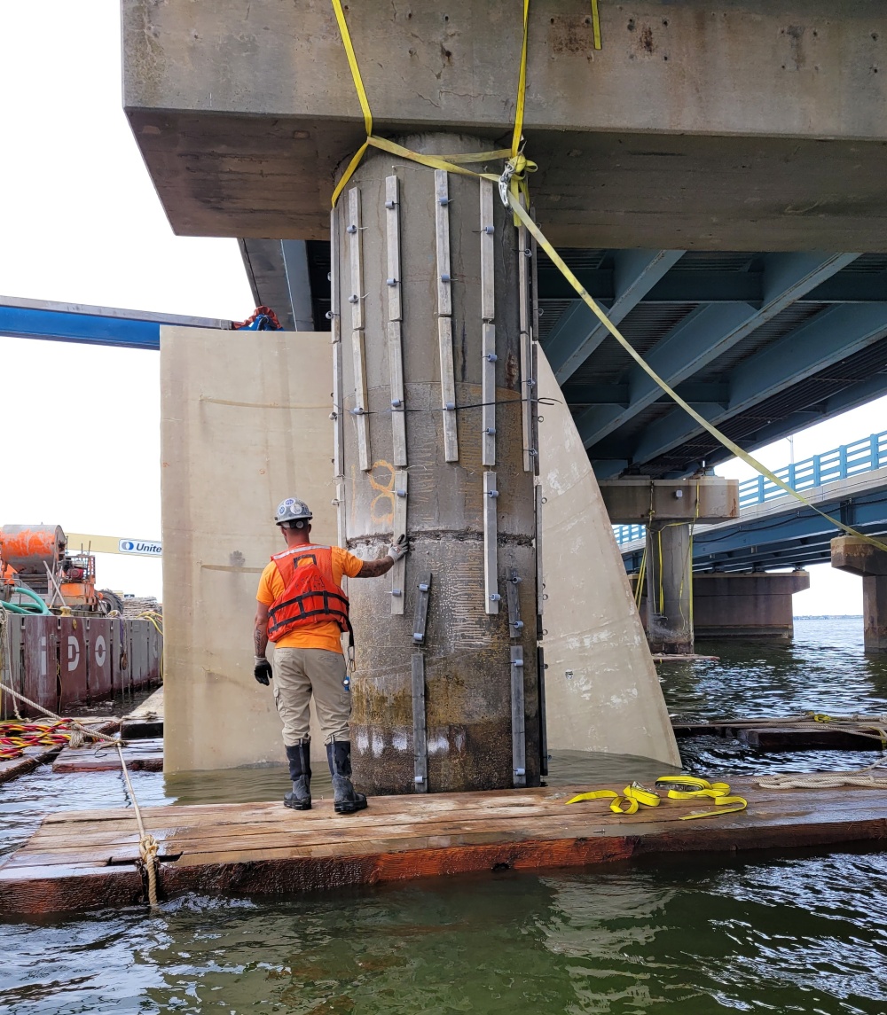
Solution: Cathodic protection (CP) jackets with welded wire fabric (WWF) reinforcing were selected to stop corrosion of the pile reinforcement and add strength to the severely deteriorated piles
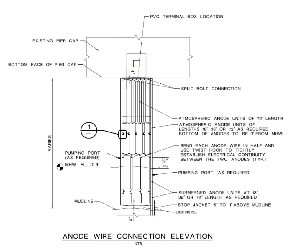
The CP jackets extended from the top of the pile, just below the cap, to the mudline to fully encapsulate the existing cracks. Due to the variable elevation of each bent, the CP design had to account for three different environmental conditions; submerged, tidal, and atmospheric exposure. Each of these environments results in different corrosion mitigation requirements and design considerations. In particular, different galvanic anodes had to be used in each environment to ensure that they remained active in protecting the structure. During galvanic CP design, it is critical to understand how the anode will be activated. In submerged and tidal saltwater environments, saltwater can keep the anodes active. In the atmospheric environment, because there is no direct water exposure, the anodes must be self-activated. The corrosion and durability consultant evaluated each pile’s environment to ensure the CP system was designed to provide the most effective protection for a 20-year anode design life.
An additional challenge during the design phase was that additional anode output current was required in the structural jackets, compared to the non-structural jackets, and at the top of each pile. The top of each pile had more steel reinforcement to accommodate the connection to the cap. This additional reinforcement at the top of the piles and the WWF in the structural jackets increased the total metal surface area, affecting the required current output from the CP jacket to properly mitigate corrosion.
Distributed galvanic anodes were selected for this project. Since these anodes are manufactured specifically for marine or atmospheric exposure and come in discrete strips, their number and quantity could vary within the jacket to meet the service life requirements and environmental operating conditions.
Project Scope
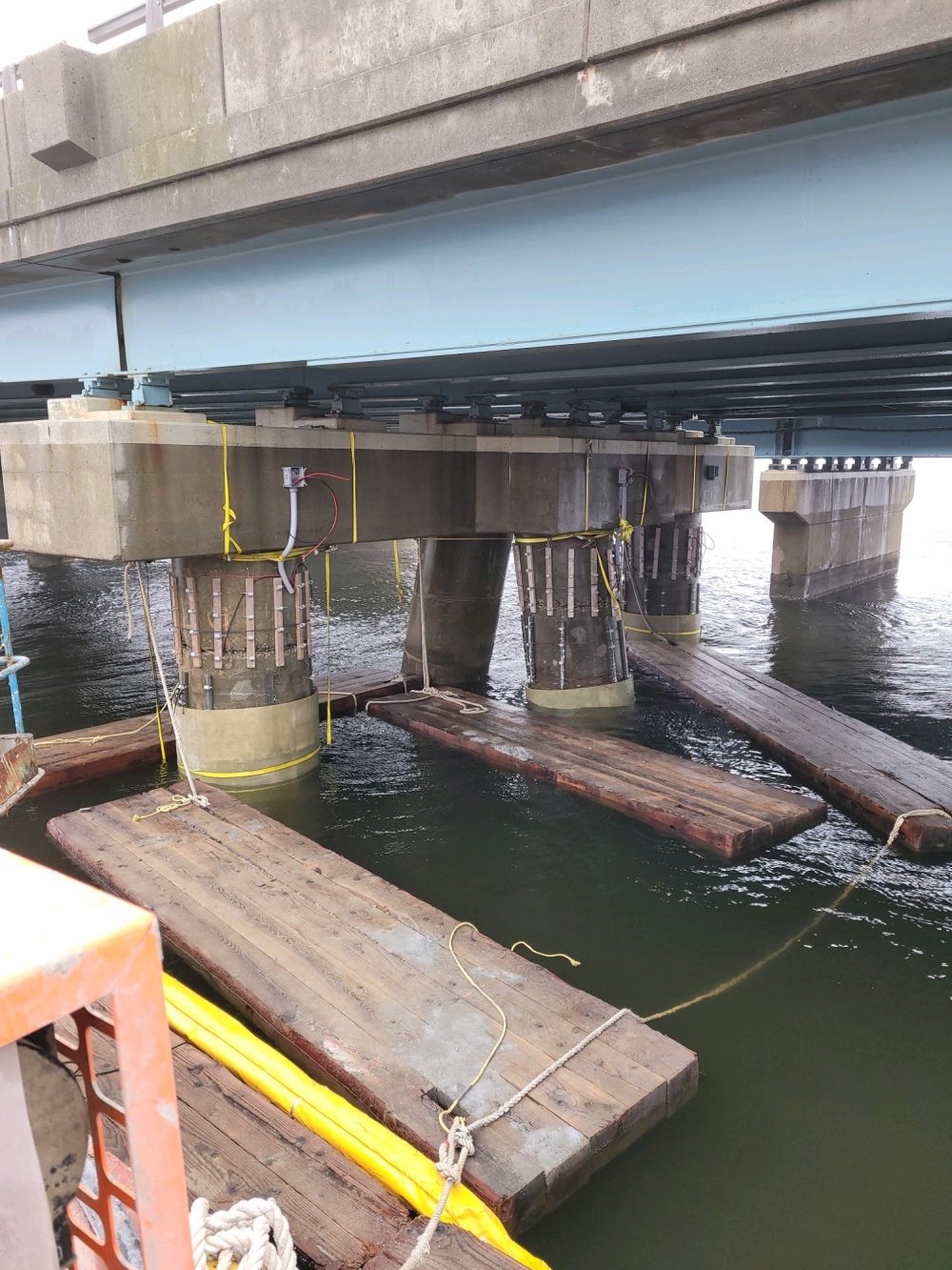
The installation of the jackets consisted of the following procedure:
- Establishing electrical continuity of the reinforcing steel by chipping a horizontal grove in the concrete pile to expose the reinforcement. This allowed for brazing a wire to the prestressing strands and the spiral stirrups to establish electrical continuity of all the reinforcement within the pile.
- Attaching distributed anodes to the pile and connecting all the anodes together to header wires.
- Attaching two structure wires to the original pile reinforcement to complete the cathodic protection circuit with the anodes. Two additional structure wires were connected to the welded wire fabric for the structural jackets.
- Installing the stay-in-place PVC or FRP jacket forms around the pile.
- Tremie pump grout to fill the void between the forms and the original pile, creating an ionic coupling for the anodes to provide CP protection to the piles.
Project Summary
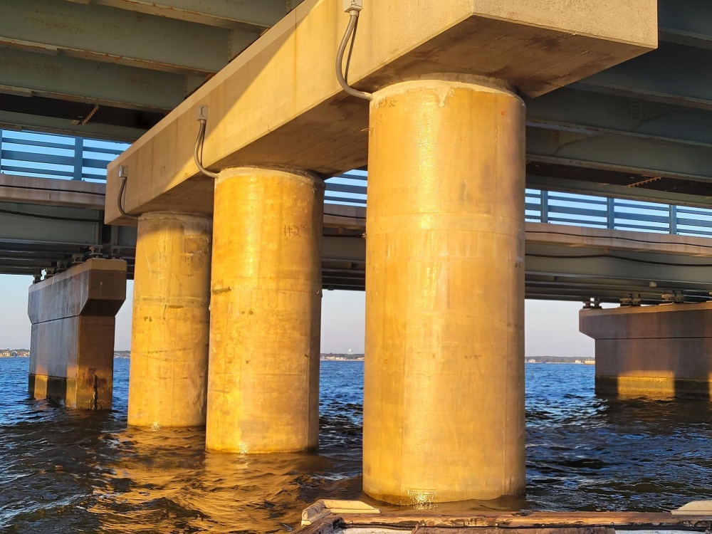
| Over 12 months of construction, 112 cathodic protection jackets were installed on Tunney Bridge.
Construction was completed in December of 2022 and all the jacket anodes have been activated to provide cathodic protection to the piles of the Tunney Bridge. The bay is exposed to regular storms, cold and windy winters, and extremely busy summer months along the Jersey Shore. Given these challenges, all work was accomplished within a year using barges without disruption or impact to traffic or the public.